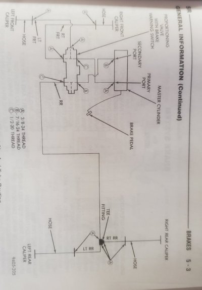
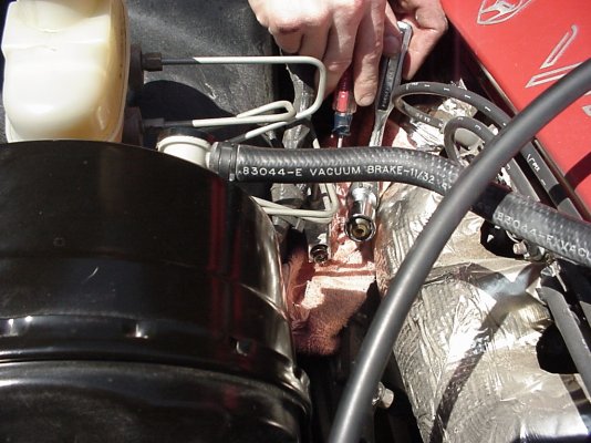
Got a question. I’ve got a gen2 GTS (non ABS) and I’m running gen 3 front calipers with IPSCO brackets and gen2 fronts on the rear. I’m going to install an adjustable proportioning valve to control the rears and make adjustments based on track conditions, pad compounds, etc.
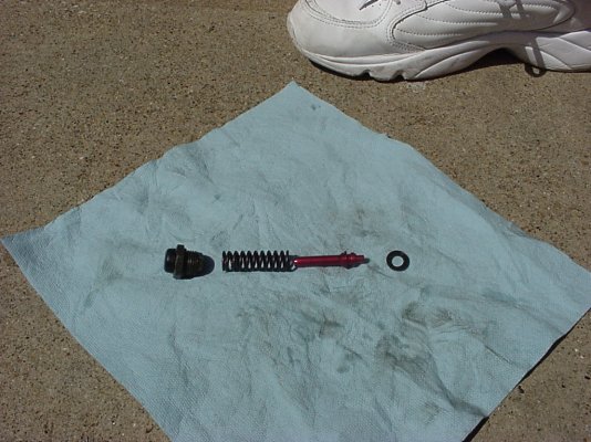
The stock prop valve uses a shuttle valve for the rear circuit (that most people gut) and from my understanding full brake pressure goes to the rear brakes until it overcomes the spring pressure of the shuttle valve and starts restricting the rear brake pressure (in the manual this is referred to as the knee point).
So if I remove the spring/ball for the rear circuit from the OEM prop valve, is it just going to feed full brake pressure to the rear brakes all the time? Or is there some proportioning built into the housing of the OEM proportioning valve and the spring/ball assembly just controls the knee point?
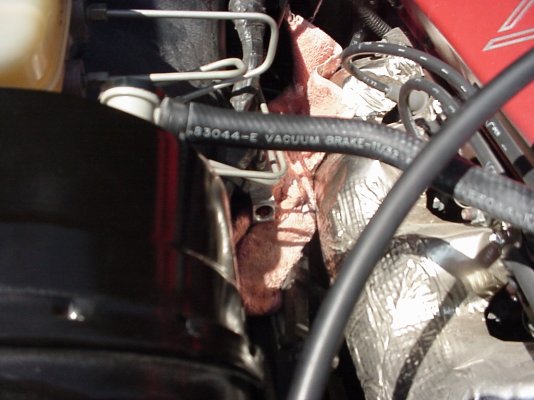
The reason I ask is if removing the ball/spring results in full pressure to the rear brakes all the time then I can put my adjustable prop valve BEFORE the OEM one, gut the OEM spring assembly and still retain the safety shutoff and brake warning light aspect of the stock prop valve. Plumbing between the reservoir and OEM prop valve is also easier to access and farther from the exhaust manifold.
Normally you would always install an adjustable prop valve AFTER any OEM prop valve, but if (after gutting it) the OEM prop valve is just allowing full brake pressure to the rear circuit then it shouldn’t matter…
Anyway if someone that has done this or knows if the OEM valve after gutting it is just a “straight through” to the rear circuit, please chime in.


