DRB III Reverse Engineering Project

OP
OP
MoparMap

MoparMap

VCA National President
VCA Officer
Joined
Jan 7, 2013
Posts
2,501
Reaction score
307
Location
Kansas
A little progress and a little setback on this one. I ended up bricking one of my sensors somehow in all of the testing I was doing. Must have shorted some pins or put too much voltage on the wrong one or some weird command sent. Especially weird since the sensor is after the splitter box and the splitter box manages voltages and stuff like that, so seems even more unlikely that the problem would have been a bad connection. I guess I could have just insulted it in computer language with some message I sent that messed things up. I still have the second one, but am a bit more gun-shy about just throwing random code at this one now.

That being said, I think I've finally got the start of a program going to read signals on a Windows based computer. I have something that will send a command and read a response to a text box, but at the moment I'm just testing a closed loop where I'm wiring the Tx line directly to the Rx line of the port on my computer, so no sensors involved at all right now. It also doesn't continually update just yet as I'm trying to remember how to code all over again and I never really interfaced with hardware ports to begin with. I can get it to update a text box with a button click though, and I have user selectable ports, so at least that's something. Might try plugging a sensor in again to see if it's actually doing what I want. From there I'd like to get it to the point where you click "start" and it just constantly updates the box as you tilt the sensor. Seems like something within my reach at least, just have to find the right code online to help me figure out how to run background tasks like that.
 
OP
OP
MoparMap

MoparMap

VCA National President
VCA Officer
Joined
Jan 7, 2013
Posts
2,501
Reaction score
307
Location
Kansas
Well, a little more progress and a little less at the same time. I've got a program going now that will constantly update the readout and works when the cable is looped back on itself at least, but I'm not having any luck actually getting a response from the sensor yet. So assuming I can figure out what is going on there I think there is still some promise in this endeavor. Guess I just have some more signal snooping to do so I can see if I can figure out where the communication is breaking down.
 
OP
OP
MoparMap

MoparMap

VCA National President
VCA Officer
Joined
Jan 7, 2013
Posts
2,501
Reaction score
307
Location
Kansas
Success! After all this time trying to figure out why it wasn't responding it was something as dumb as me sending it the wrong commands. It was looking for 03 04 58 02 5E in hex and I was sending it 04 05 58 02 5E. I know the sensors responds with 04 05 58 and thinking back I was originally sending a fake response just to see if my readout was working right. I stared at this stupid thing and tested it so many times I'm not sure how I missed something that simple.

All that said, I think I've got just a little more work to do. I was playing with the DRB III some more today to double check that it didn't have some kind of startup signal or something and while I was there I decided to give the "zero" function a try to see what it did. As it turns out, it does send a unique message to the inclinometer, so it would appear the inclinometer is the one that stores the zero, not the DRB III itself. Looks like it should be easy enough to mimic this behavior with some buttons, but I know the zeroing process is a two step one where you rotate the sensors 180 degrees between. I want to double check and make sure that it doesn't send a unique signal for each step of the process.

The other issue I'm having is debatable about whether it's really a problem or not. At the moment, with the math and outputs I've taken, the readout goes a little wonky above 45 degrees and jumps up to 180. So I'm guessing what I should probably be doing is adding some kind of offset to the value if I want it to read more true through the whole rotation, but that should hopefully just be as simple as taking some more raw readings with the sensor at various angles and working out the math. Realistically you'd probably never need more than 10 degrees out of a sensor if you're just using them to measure caster, but in the long run it is just a sensor and might as well be able to use it for more than that. You could probably use them to measure camber as well if you had a fixture to attach them to, though again those are going to be some small values.

Total side note, but I'm pretty sure I have a good idea why the sensors are oriented 45 degrees. Kind of like if you are using a tape measure and you start on 1" instead of the end. Since we're talking small angles to begin with, it's likely measuring in the middle of the sensor's useful range so that you aren't balancing on the edge of zero / 180 all the time when you are level. Having it rotated all the time means you'd never flop the output drastically.

Also, the one sensor I thought I might have killed is apparently not entirely dead. It still seems to not respond very well to a computer, but I plugged it into the DRB III the other day and it came alive again after a few tries. Thinking I must just have a bad connection somewhere, but glad to see it's not totally dead. Was kind of thinking it would have been hard to **** since the vast majority of testing I've done is with the switch box in front of it, so if anything would have broken from an incorrect connection I would have expected it to be in there.
 
Last edited:

deyan

Enthusiast
Joined
Sep 20, 2019
Posts
28
Reaction score
1
Location
Royal Oak, MI
Very cool! Yeah for what they are used full range is probably not needed but yeah would be great to unlock the full capability. I would be totally happy with 45 degrees
 
OP
OP
MoparMap

MoparMap

VCA National President
VCA Officer
Joined
Jan 7, 2013
Posts
2,501
Reaction score
307
Location
Kansas
I also found out the zero function is way more complicated than I was originally hoping. The first step is straightforward enough and only 3 commands, but the second step is a lot more data being sent that I'm still trying to understand. I think I know what is going on in a big picture perspective, but trying to decode that in raw hex values isn't quite as intuitive. The sensor is in fact the one that carries the zero I am quite sure. Ideally I need to be logging the traffic both ways between the sensor and the DRB, but I don't really have a good way to do that and keep timestamps with my setup right now. I'm basically just splicing wires and tee'ing the signal off to feed into my computer right now, but I can only pick the Rx or Tx line at one time. If I had a second USB serial adapter (which I might somewhere, need to dig around as I could have sworn I did), I could put one line on each adapter, but it would still be a little bit of a guessing game on figuring out when each signal was coming in relative to the other.

Long story short, it looks like the zero process basically does exactly what the manual says. It looks like it's asking for the value in the first calibration orientation, rotating, asking for the value again, then doing some kind of what I presume is a write command. There are some portions of that write command that are always the same all the time, but the parts that are changing are changing very minimally, so it's hard to figure out exactly how much of that data is an actual value that is being written and how much of it might just be a command or memory address or something. I tried zeroing at a noticeable angle, but the values are still only changing by a few bits. I guess realistically even if you zero it at 45 degrees, the process has you flip the sensor 180 between measurements, so it would take the average between the two values and should theoretically still give you roughly the same actual zero. So at this point I can replicate the zero command easily enough, I just don't know what math is actually happening to be able to 100% replicate what the DRB does just yet.

The alternative option is a software zero that would just apply an offset to whatever the sensor spits out. That would be pretty easy to implement, though I feel like it might be missing something. In some of the testing I was doing yesterday when I finally got the sensor reading values out, it seems like my scale was just slightly off. Like it would read about 0.1 degrees more per 10 degrees as I was rotating it compared to my other digital inclinometer. So 10 deg on my digital one would read 10.1 on the DRB one and 50 on the digital one would be 50.5 on the DRB one. I'm not sure if the zero function might help with this or not, but I also haven't checked the output against my digital inclinometer after all the zero stuff I was messing with yesterday. I need to get some fixed wedges as well so I'm not trying to hold things with my hands since that could very well have something to do with it too.
 
OP
OP
MoparMap

MoparMap

VCA National President
VCA Officer
Joined
Jan 7, 2013
Posts
2,501
Reaction score
307
Location
Kansas
So I guess the main question right now is how comfortable are you with making your own cable? If you wanted to try I could just send you the cable diagram and the program as I have it now and can keep working on it in the meantime so you can actually use your sensors while I try to get things more fully featured. I think I could build in a software zero function pretty easily that would just offset the value, but it would mean you would have to zero the sensors every time you want to use them, assuming they aren't already reading level that is.

At the moment the cable design I have going is pretty simple, but will only read one sensor. I have a plan on how to include a switch that would let you swap between them, but it would still just be reading one at a time. Could also just swap between plugging in one or the other, but that might not be the best for the connectors in the long term if you did it a lot. If you don't have the equipment to build a cable (pretty much just a soldering iron), I can probably make one for you. Haven't priced anything out, but it's just two DB9 connectors and some wire, plus whatever you want for the power connection (could just be flying leads or some kind of connector if you want).
 

deyan

Enthusiast
Joined
Sep 20, 2019
Posts
28
Reaction score
1
Location
Royal Oak, MI
Yeah I would definitely be willing to try it, I can solder, I am not the greatest at it, but I can put few wires together lol. That would be awesome though! I don't think I have any db9 connectors but i am sure it'll be easy to source few
 
OP
OP
MoparMap

MoparMap

VCA National President
VCA Officer
Joined
Jan 7, 2013
Posts
2,501
Reaction score
307
Location
Kansas
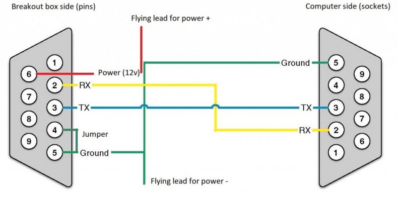
Okay, I'll try to get a little schematic drawn up and you can test it and let me know if it works for you. It's pretty straightforward, three straight through cables, one jumper, and some flying leads for power.
 
OP
OP
MoparMap

MoparMap

VCA National President
VCA Officer
Joined
Jan 7, 2013
Posts
2,501
Reaction score
307
Location
Kansas
Here's a drawing of the adapter cable setup. You'll need one male DB9 and one female DB9. Pins 2, 3, and 5 go straight through from one connector to the other. On the inclinometer breakout box side pins 4 and 5 need to be jumpered (doing this will only allow you to read from the sensor plugged into the "left" port on the breakout box). If you wanted to read from the "right" port on the breakout box you need to put 5V on pin 4. Pin 6 on the breakout box connection is 12v power. You'll need another wire coming off of any of the ground connections for the negative side of the power supply. This just ensures that all devices are using a common ground for reference. You could take this off of pin 5 on either connector so you don't have too many wires stack on a single tiny pin. Let me know if this all makes sense. I can try to take a picture of the one I made as well, though it's not the prettiest as it was just spare stuff I had laying around.

My long term plan was to build a 5v regulator into the cable with a switch that would feed pin 4 either ground or 5v based on what position it's in, but that can come later. Thinking about trying to make one myself to see if I can make it look nice and potentially even sell it as a kit some day.
 

Attachments

  • Inclinometer Cable.jpg
    Inclinometer Cable.jpg
    60.8 KB · Views: 8

deyan

Enthusiast
Joined
Sep 20, 2019
Posts
28
Reaction score
1
Location
Royal Oak, MI
Awesome, thanks for the diagram and all the work on this, I'll try and order the parts this week, and I am sure I'll have a bunch of questions, but should be fun little project lol
 

deyan

Enthusiast
Joined
Sep 20, 2019
Posts
28
Reaction score
1
Location
Royal Oak, MI
So I got the db2 connectors but time has been at a premium, I am hoping I'll find some time soon to create the harness!
 
OP
OP
MoparMap

MoparMap

VCA National President
VCA Officer
Joined
Jan 7, 2013
Posts
2,501
Reaction score
307
Location
Kansas
No worries, I haven't really done much on my side either. I'll see about making a software zero function for the first "release" of the program for you. That should make it reasonably useable to start with I would hope. Haven't really played around with the real zero function in a while. I'm not sure how it handles zeroing two units at a time either. I got to thinking that maybe some of the wall of values I'm seeing come out of the DRB III might have something to do with that as well. I'm not sure it knows whether you have 1 or 2 sensors plugged in when you do the zero stuff, so that might explain some of the extra code.
 

deyan

Enthusiast
Joined
Sep 20, 2019
Posts
28
Reaction score
1
Location
Royal Oak, MI
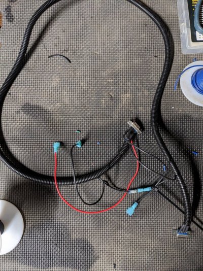
So I finally got around to building the harness, it's been a bit of a crazy year, but I finally have a bit of time to mess with it. The one part that still confuses me a bit is pin 4 and 5. Right now I have them jumpered so that I can connect to either 4 or 5, but if I am connecting to the left port do they both need to be connected? And right port, they both get disconnected and 5v goes into pin 4. Is that correct? Where am I getting the 5v from?
 

Attachments

  • PXL_20230127_012421036.jpg
    PXL_20230127_012421036.jpg
    280.5 KB · Views: 7
OP
OP
MoparMap

MoparMap

VCA National President
VCA Officer
Joined
Jan 7, 2013
Posts
2,501
Reaction score
307
Location
Kansas
Yeah, I guess the "easy" way to think about it is if you have ground on pin 4 you are getting readings from the left sensor and if you have 5v on pin 4 you get readings from the right sensor. You would have to supply the 5v yourself from somewhere though, so I'm not sure if it's worth dealing with the hassle unless you wanted to build a dedicated power supply for the harness as well. You could probably make something that has a 12v and a 5v output and have a switch that toggles the 5v output between power and ground, but I found it easier to just only read one sensor at all. You can still hook both up to your car and just alternate plugging them into the breakout box though. More fiddling to get values, but less electronic work to get there.
 

deyan

Enthusiast
Joined
Sep 20, 2019
Posts
28
Reaction score
1
Location
Royal Oak, MI
Okay yah that makes sense! I'll keep it simple for now, but adding a switch in the future might not be too difficult!
 

GTS Dean

Enthusiast
Joined
Jul 22, 2000
Posts
3,906
Reaction score
300
Location
New Braunfels, Texas
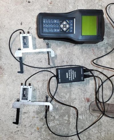
Are either of you using the magnetic switch box that the two individual inclinometers connect to? I assume so, but haven't seen a photo of it here.

I really appreciate what you're trying to do here, but I've about decided the best strategy for most folks is to epoxy a strip of gauge steel onto the aluminum adapter brackets and use $15 magnetic digital inclinometers in place of the DRB-III. If you can get caster in-spec and within 0.2* side-side, you're in good shape.
 

Attachments

  • Full rear setup.jpg
    Full rear setup.jpg
    117.8 KB · Views: 18
Last edited:
OP
OP
MoparMap

MoparMap

VCA National President
VCA Officer
Joined
Jan 7, 2013
Posts
2,501
Reaction score
307
Location
Kansas
Yeah, my setup and the pictures I posted at the very beginning of this thread are actually the inside of the switch box. I think some of the caster brackets are actually already steel to begin with. Some of mine are aluminum and some are steel at least.

I mostly just got into the idea because I already had the parts. I bought the suspension service kit (Miller tool 6990) primarily just to get the various bushing installation and removal tools as that was the most cost effective way to get all the pieces. Just so happened to come with the inclinometer parts, and seeing a DB9 style cable on the end of it just got my engineering brain working. It has snowballed quite a bit from there though. The setup feels overly complicated from what it could have been, but then again this was made in the 90s, so technology might not have been at quite the same level and they may have been reusing parts or had some other limitation. Just seems bizarre to me that the sensors aren't your typical 5v or 4-20ma output, but I'm guessing maybe the actual sensing element itself is and they just had to put a microcontroller in line to convert that to something the DRB III could read natively.
 

deyan

Enthusiast
Joined
Sep 20, 2019
Posts
28
Reaction score
1
Location
Royal Oak, MI
Dean yah, you are probably right, and the reality for me is that I use shims instead of the cam bolts, so the rear caster isn't really a problem anymore, and the front is pretty easy to measure with camber/caster gauge. But it would still be nice to get the tools in the kit working, even if it's for just the fun of it. I do appreciate all the work MoparMap has put into this so far. I wish I had more free time to test it out and contribute but free time has been hard to come by lol, and my engine is currently torn up so that doesn't help. Maybe when I start setting up the car for the season I can test some of it out.
 

GTS Dean

Enthusiast
Joined
Jul 22, 2000
Posts
3,906
Reaction score
300
Location
New Braunfels, Texas
Good to hear from you! I use the CC alignment plates too! Production car tolerances on the ear stops are pretty crappy, but once you get your caster right at each corner, it's pretty easy to get the camber you want and hold caster.
 

ninetyfive

VCA Member
VCA Member
Joined
May 25, 2023
Posts
64
Reaction score
10
Location
Chicago
@MoparMap I would think one of these should help intercept and decode the data.


OP
OP
MoparMap

MoparMap

VCA National President
VCA Officer
Joined
Jan 7, 2013
Posts
2,501
Reaction score
307
Location
Kansas
@MoparMap I would think one of these should help intercept and decode the data.


Definitely a more elegant solution than what I put together, but also pretty pricy for my little DIY project. I looked at trying to build a logic analyzer with something like a Raspberry Pi, but the main issue with that is just the voltage level limitations of the Pi. You could do a level shifter and other stuff to make it work, but it just gets kind of unwieldy the further you dig into it. A dual channel oscilloscope with a recording function might be able to do the job as well, would just take a little more brainpower to do the conversion of the signal into actual binary/hex/whatever format.
 
OP
OP
MoparMap

MoparMap

VCA National President
VCA Officer
Joined
Jan 7, 2013
Posts
2,501
Reaction score
307
Location
Kansas
Are the TX/RX lines at 12V or 5V?

Depends where you are measuring them. Out of the sensor itself they are 5V, but out of the splitter box they are 12V. There is an RS232 converter chip in the splitter box though, which is what accounts for the change. So you can talk to the sensors directly via something like an Arduino or Raspberry Pi (with a level shifter for the Pi), or you talk to the splitter box via a standard 9 pin serial port. The only tricky part with the serial port is you have to supply power as well, so it's not as straightforward as just plugging the DB9 into a computer and opening a terminal.
 

ninetyfive

VCA Member
VCA Member
Joined
May 25, 2023
Posts
64
Reaction score
10
Location
Chicago
Makes sense. So a logic analyzer in the middle should capture the commands and reaponses.
 
OP
OP
MoparMap

MoparMap

VCA National President
VCA Officer
Joined
Jan 7, 2013
Posts
2,501
Reaction score
307
Location
Kansas
Yeah, that was the ideal setup I was going for originally. I sort of cobbled one together by just splitting the connection between the DRB and the junction box and running that into a separate computer. Probably not the best idea ever, but it worked well enough to see the commands being sent via a terminal style application. That's how I got the couple of commands I have currently at least. A real logic analyzer that could record the signals with timings between them would be awesome and the ideal setup for sure. I have a little pocket oscilloscope, but it doesn't exactly record stuff that well or do multiple channels. I looked at some Raspberry Pi software that made it a sort of logic analyzer/oscilloscope (not exactly though as the Pi doesn't have analog input, but would work for digital logic of acceptable voltage levels), but didn't get too deep into that one. Thought about buying a real logic analyzer, but at several hundreds of dollars it was more than I felt like spending for a novelty. I don't do this kind of stuff enough to warrant the spend, I just tinker and know enough about electronics to be dangerous, lol.
 

Members online

Forum statistics

Threads
153,609
Posts
1,684,948
Members
18,175
Latest member
bathurst68
Top