Hi
The speedo on my 1999 GTS need to be calibrated due to bigger wheels and different gearing.
I just got my yellow box and tried to install it without succes. I was following the instruction and those are the problems I run into:
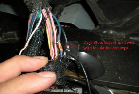
1. In the harness leading to the black PCM connector, I was supposed to use the dark blue with gray stripe to feed the yellowbox. There are two blue/gray cables and I don´t know which one to use. In the picture från the instruction, it shows a lighter blue even though it says dark blue. Am I supposed to use the lighter one? One of the blue ones on mine is maybe a little bit lighter, you can barely see the difference.
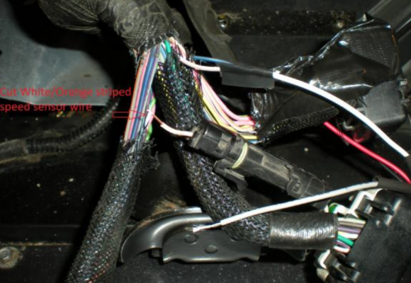
2. The instruction says that the white wire with orange stripe in the harness leading to the white PCM connector is the speed sensor cable and should be easy to find because it has a separate connection. Mine doesn´t. I found the white/orange wire but it does not have a separate connector, if it isn´t hidden behind tape but I don´t think so. Is this a problem?
Everything else I did exactly as the instruction said but the speedo was dead when I test drove it. The instruction says that the yellowbox is supposed to light up when connected and the power is turned on but my doesn´t.
Where to start the troubble shooting? Picrures are from the instruction.
The speedo on my 1999 GTS need to be calibrated due to bigger wheels and different gearing.
I just got my yellow box and tried to install it without succes. I was following the instruction and those are the problems I run into:
1. In the harness leading to the black PCM connector, I was supposed to use the dark blue with gray stripe to feed the yellowbox. There are two blue/gray cables and I don´t know which one to use. In the picture från the instruction, it shows a lighter blue even though it says dark blue. Am I supposed to use the lighter one? One of the blue ones on mine is maybe a little bit lighter, you can barely see the difference.
2. The instruction says that the white wire with orange stripe in the harness leading to the white PCM connector is the speed sensor cable and should be easy to find because it has a separate connection. Mine doesn´t. I found the white/orange wire but it does not have a separate connector, if it isn´t hidden behind tape but I don´t think so. Is this a problem?
Everything else I did exactly as the instruction said but the speedo was dead when I test drove it. The instruction says that the yellowbox is supposed to light up when connected and the power is turned on but my doesn´t.
Where to start the troubble shooting? Picrures are from the instruction.